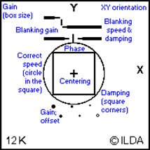
The “ILDA Test Pattern” was created to ensure a user is able to accurately tune their laser scanners to the standard in which ILDA has specified. For example, a 30K scanner should be tuned at approximately 8-degress optical or less.
What is the correct use of the ILDA Test Pattern?
There are a number of parameters measured by the ILDA Test Pattern. The most critical one for speed-related issues is a circle that is drawn outside a square. As the scanner speed is turned up, the scanner can’t accurately track the circle, so the circle gets smaller. When the circle is just touching the center of the square’s sides, this indicates the circle’s tuning.
It is impossible to scan both fast and wide. This is why the ILDA tuning standard also specifies the angle at which the test pattern is scanned. For 30K-tuned scanners, this angle is "about 8 degrees optical or less".
(At 8 degrees, the width of the test pattern is roughly 1/7th the scanner-to-screen distance). Pangolin's specifies True 50K scanners as meeting the ILDA requirement at 7 degrees. In addition, there are other elements of the test pattern which are important, such as having the circle be circular and not elliptical.
Test pattern parameters
The ILDA Test Pattern measures many parameters. But the circle-in-the-square test is the most important for measuring scanner speed. The projected circle must be touching the inner square's sides, as shown at right. (On your computer monitor, the circle will be outside the square as shown above.) It is also important to specify the scan angle. The larger the scan angle at which the scanner correctly shows the circle-in-the-square test, the better.

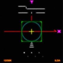
Correct tuning
The most important speed-related element is the blue circle around the outside of the green inner square. The circle is carefully drawn. When the blue circle is just touching the midpoint of the green square's sides, this is the correct, ILDA-compliant speed.

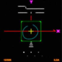
Scanning too fast
At too-fast speeds, the blue circle is inside the green square.

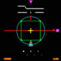
Scanning too slow
At too-slow speeds the blue circle is outside the green square as shown above.

What does it mean when a system can show the ILDA Test Pattern? Just that is can be displayed, or that it is displayed a certain way?
In the laser display industry, the ILDA Test Pattern is generally recognized as the standard of comparison. A computer might be able to output the points in the ILDA Test Pattern at 60,000 points per second (or more), and the scanner might show most of the ILDA Test Pattern acceptably, but this is not sufficient -- some of it is unacceptable.
If someone says "this scanner shows the ILDA Test Pattern at such-and-such a speed and angle", laserists reasonably assume that the scanner correctly shows all parts of the test pattern (unless explicitly stated otherwise).
What is the difference between “60K pps” and “ILDA 60K pps”?
Saying "my scanner runs at 60K pps" means that it can show something, at some scan angle, when a computer is outputting points at 60,000 pts/sec.
This may be a true statement, but it is meaningless. To be useful to laserists, statements about scanner performance must also indicate what images are being shown, at what scan angle, and how well they are being reproduced.
Saying "my scanner runs at ILDA 60K pps" tells the listener that "this scanner can accurately reproduce all parts of the ILDA Test Pattern, including the circle just touching the square’s sides, when the test pattern is run at 60,000 points per second at a scan angle of 8 degrees or less."
Is the ILDA Test Pattern the best test pattern available?
The ILDA Test Pattern is an industry standard, and is the most-agreed upon measure of scanner performance. So yes, it is the best commonly-available test pattern.
Does the ILDA Test Pattern accurately characterize scanner performance?
It has done so in the past. But one problem with the circle-in-the-square test is that it measures scanner performance at only one point in the scanner’s performance regime. This is like measuring a loudspeaker’s performance by the accuracy at which it plays middle C. While helpful, it does not tell the whole story.
Measuring at one point has worked so far because in the past the scanner performance curve has been similar at 12K, 30K and even 36K. If performance is known at one point, it can be inferred at most other points.
But new scanners or scanner amp tunings may come out which change the shape of the curve. For this reason, it may be necessary for the laser display industry to develop a consensus on new test patterns that give additional data.


